Guest Post by Michael E. Beall the “CAD Trainer Guy” of the ‘http://www.cadtrainerguy.com/
 I was training some folks at Cummins Engine Plant in Indiana, and one of the guys brought in a surveyor’s plan for his property asking how to enter the distance and bearing values from the site plan into AutoCAD.
The key to the exercise is knowing what AutoCAD requires when you type in the distance and bearing values. Surveyor’s Units are entered using the following format:
 N 0d00’00” E
MEMO: Although setting the drawing units to Surveyor’s is not required to draw with distance and bearing values, you will find the options in the Format menu >Units.
The following exercise incorporates the DYN feature, just so you can understand how the dynamic entry feature works.
 How to Draw with Surveyor’s Units
1. Begin a new drawing, then turn on Dynamic Input (DYN button) on the Status bar.
2. Launch the Line command, then specify the first point.
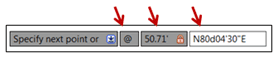
 3. For the next point, enter the following value: @50.71′<N80d04’30"E
Breaking it down …
@ After specifying the start point, @ says the following values are to go from where you’re at.
Distance Enter the distance for that section of the property line (or road or culvert center line, etc.)
This says the angle or bearing value is to follow …
Bearing Enter the bearing values in the proper format for Surveyor’s Units shown in the example, above.
“These steps are for the ‘general AutoCAD user looking to draw accurate geometry from provided surveyor coordinates and bearings. For those of you needing ‘Professional Grade’ mapping abilities, you may want to consider AutoCAD Map”.
But is there a way to automate the entry of calls from a survey when there are a very high number of them, like say 60-100 different bearings and distances?
Chris,
Did you ever get an answer to your question? I can’t even get the line command to work with bearings. Just curious if you had any progress.
I have a similar question. I’m helping a friend look at potential uses for some property he wants to buy, and asked him to get some property line bearings and distances for me. Instead, he gets me corners, thus:
SW Corner 33˚32’55 N x 95˚43″40.6 W
NW Corner 33˚32’58.6 N x 95˚43’40 W
NE Corner 33˚32’58.9 N x 95˚43’38.3 W
SE Corner 33˚32’55.1 N x 95˚43’38.3 W
I’m familiar with plotting by bearing and distance, but it seems like I need to plot these points as points, then connect the dots. How would I do this (using ACAD 2002)?